
pv magazine test: Big Modules, New Beginnings
By George Touloupas
This article was originally published in pv magazine – November 2021 edition. Learn more about the pv magazine test here.
Earlier this year, the pv magazine test outdoor array in Xi’an, China underwent extensive modifications so it could accommodate the form factors and electrical characteristics of new modules based on larger wafer formats. George Touloupas, Senior Director of Technology and Quality at CEA, takes us through the new system and the reasons why the modifications were needed, as well as the role of newly installed microinverters supplied by AP systems.
Extensive modifications to the pv magazine outdoor field test were necessary because of the proliferation of new module designs, form factors and electrical characteristics, all stemming from the introduction of bigger wafer sizes.
The mounting structure had to be modified to accommodate big bifacial modules, and the optimizers and DC/AC inverters were replaced by new microinverters supplied by AP Systems (see Image 1 below), which are capable of maximum power point tracking across the broader range of electrical characteristics of the new generation of modules.

Image 1: AP Systems microinverters installed at Xi’an test field
After operating the newly configured field for three months, we noticed some anomalies in the energy yield ranking of several bifacial samples, and conducted a detailed investigation to identify the root causes. As the available data did not comply to our standards of accuracy, we decided to skip the publication of the monthly yield data for August and September, until we were certain the issue was rectified. We apologize to our readership, and we look forward to continuing to publish high quality data from the Xi’an test field from next month, as the new setup has been finally completed and the issues rectified, after some long delays due to a longer rainy season in Xi’an and consecutive holidays in China.
This article describes the field modifications in more detail and the reasons that they were necessary, the role of the new AP Systems microinverters, and the challenges we faced during implementation. The initial configuration from 2018 had each module connected to one Huawei power optimizer (Sun2000P) via a precision class 0.5 meter, that captures the voltage and current values of each module every few seconds, with the optimizer driving its operation at the maximum power point (MPP).
The optimizers were then connected in series, feeding the DC current to a grid connected Huawei Sun2000L inverter. This configuration ensured that all modules operate at MPP, with maximum current and voltage values sampled frequently and accurately, and therefore their energy production calculated with precision. Although the optimizers were prototypes with enhanced capabilities, with maximum DC inputs of 500 W for Pmax and 15 A for current, they could not support modules with higher currents, which are becoming mainstream. Additionally, as the current of each module is fed at the DC bus of a single string, big current deviations between the modules could affect the accuracy of the maximum power point tracker (MPPT) operation of the optimizers.
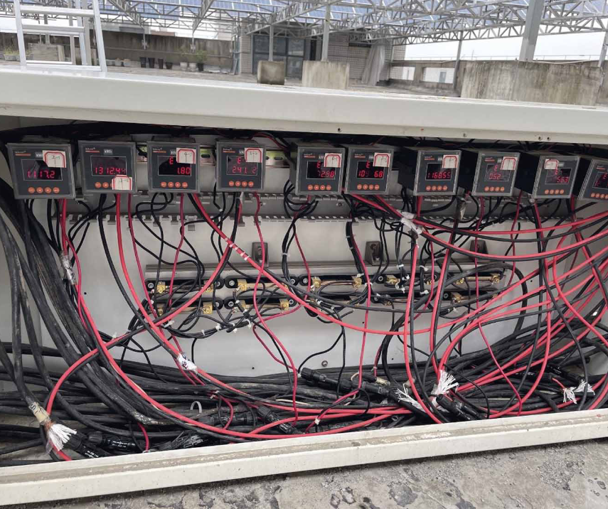
Image 2: Precision class 0.5 meters, taking current and voltage measurements every five seconds
For this reason, we took the decision to replace the optimizers with the AP Systems microinverters, which can support higher DC power and current. The initial field configuration, completed in April 2021, deployed the YC1000-3 model, which is a three-phase microinverter with four DC input channels, with 14.8 A maximum DC input and 1,190 W total DC power input, and a single MPPT for all channels. The challenge with this solution is that the connection of modules with different current characteristics to a single MPPT can impact the operation of individual modules and shift it away from the maximum power point, effectively lowering their performance. Additionally, the input current is not high enough for G12 (210 mm) modules that have 17 A-18 A of Imp (current at maximum point). So, the use of the YC1000-3 for all modules was adopted as an interim solution, as AP Systems was in the final R&D phase before the release of the DS3 microinverter which can support higher currents, but this product was not ready at the time. In order to avoid MPPT discrepancies, we decided to current-match the modules connected to the same microinverter, until the new solution becomes available. Unfortunately, oversight errors saw some modules with significant current mismatch connected to the same YC1000-3 microinverter with a single MPPT, leading to the yield anomalies we observed in the first three months of test operations.
This is not the originally intended use of AP system’s microinverters, which are designed for the residential and commercial sector, where several modules are typically connected to the same microinverter, in which case, there is no risk of underperformance due to current mismatch.
As the DS3 model became available in September, the outdoor field was partially retrofitted with the new equipment. The DS3 microinverter is single phase, with two DC inputs of maximum 20 A each, and is designed to be able to support G12 (210 mm) modules, with high current and high power.
The DS3 is in fact a product series, with several types such as DS3-S, DS3-L, DS3, DS3-H for different applications. The version selected in our testing program is one of the most powerful single phase, dual MPPT microinverters one can find in the market now. The independent MPPT for each input ensures that every module connected operates at its MPP. The specifications of the DS3 microinverters can be seen in Table 1 below.

Table 1: Specifications of AP Systems DS3 microinverter (Input Data, Output Data, and Efficiency)
As these microinverters are designed for the commercial and residential markets, the maximum available powered is not adequate for large format, utility sector modules, especially when bifacial boost contributes, as we need to 100% avoid ceiling limit of DC input in our testing program for apples-to-apples comparison among different modules, which is a higher request than applications in system operation. So the DS3 microinverters are better suited to smaller format G12 (210 mm) modules with half-cut, high current design in our testing program. The YC1000-3 microinverters were rearranged to accept a single module connection, to avoid current mismatch, and will be used for high power, lower current modules, such as M10 (182 mm) products or triple cut G12 (210 mm) products. Please take notice that the YC1000-3 has not been designed for this use, but we decided to take advantage of its special features to meet the specific needs of our testing program.

Image 3: The mounting structure had to be reconfigured to accommodate large size modules, without shading of the rear side. M10 (182mm) products can be seen in this picture.
Currently, AP Systems is developing a new product, the QT2, which is three-phase, single MPPT, with four DC inputs of 20 A capability and a total maximum power of 1,800 W. This product will be able to accept and accurately drive the MPPT of high power, high current G12 (210 mm) modules, such as 600 W and 660 W, which employ 60 and 66 half-cut cell designs respectively.
With the arrival of this product, we will have the capability to perform accurate MPP tracking and energy yield measurements for all high power, large format, high efficiency products expected to be available in the next two to three years.
George Touloupas is CEA’s Senior Director, Technology and Quality
Test Cooperation
pv magazine test is a cooperative effort involving pv magazine, APsystems, CEA, and Gsolar. All testing procedures are carried out at Gsolar’s test laboratory in Xi’an, China. CEA supervises these tests and designed both the indoor and outdoor testing procedures.


